Valve clearance
Inspect and adjust the valve clearance when the engine is cold.
- Remove ignition coils assemblies (See page IG-6 )
-
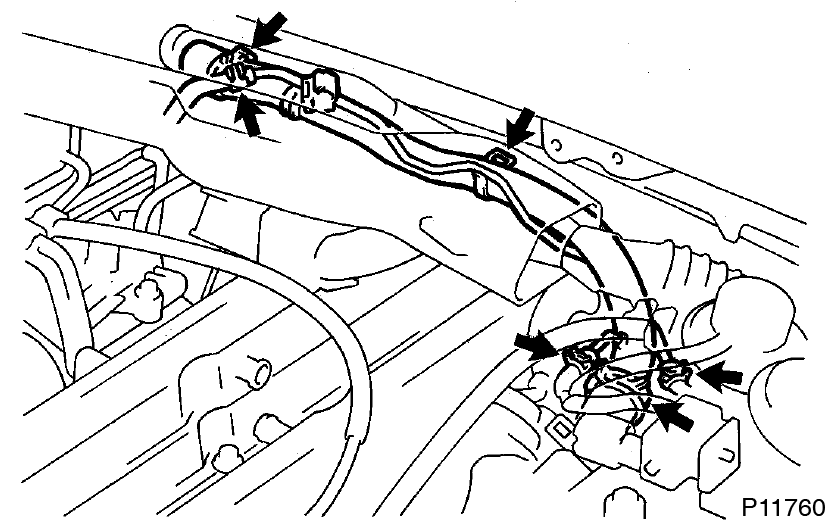
Disconnect engine wire protector from No.4 timing belt cover
- Disconnect the engine wire from the 4 wire clamps.
- Lift out the engine wire protector from the cylinder head covers.
-
Disconnect engine wire protector from cowl top panel
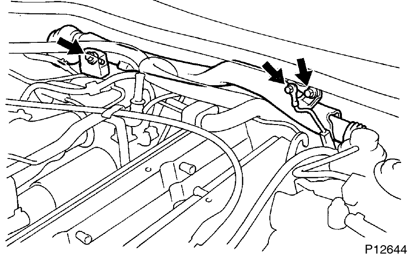
- Remove the bolt, and disconnect the ground strap.
- Remove the 2 bolts, and lift up the engine wire protector.
-
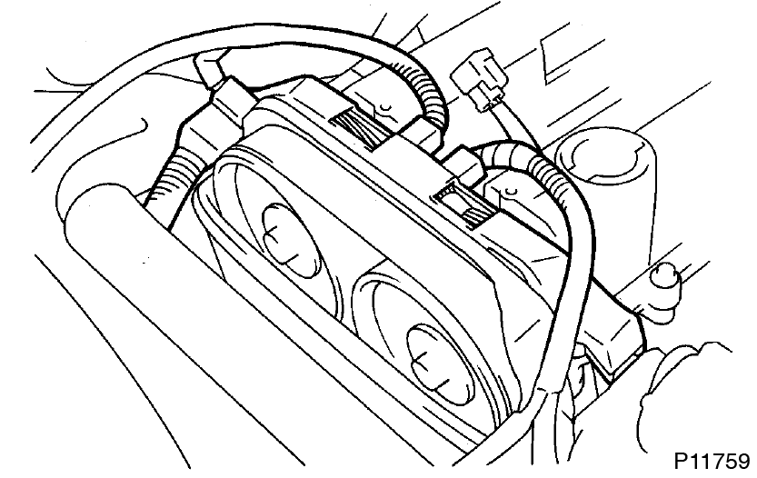
Remove IAC valve pipe
- Disconnect the 5 air hoses from the IAC valve pipe.
- Remove the IAC valve pipe from the pipe clamp on the No.1 cylinder head cover.
-
Remove No.1 and No.2 cylinder head covers
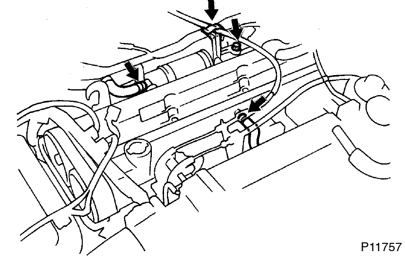
- Disconnect the cruise control actuator cable from the cable bracket.
- Remove the bolt holding the VSV to the turbo outlet duct.
- Disconnect the 2 PCV hoses from the cylinder head covers.
-
Remove the 6 bolts, 2 nuts, 8 seal washers, No.1 cylinder head cover and gasket.
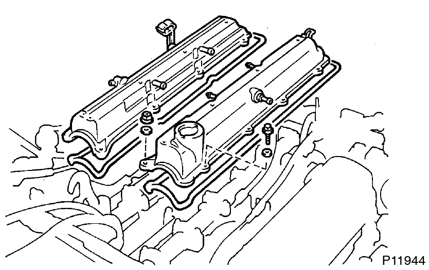
- Remove the 6 bolts, 2 nuts, 8 seal washers, No.2 cylinder head cover and gasket.
-
Set No.1 cylinder to TDC/compression
-
Turn the crankshaft pulley, and align its groove with timing mark ”O” of the No.1 timing belt cover.
Always turn the crankshaft clockwise.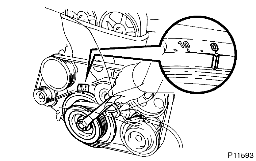
-
Check that the timing marks of the camshaft timing pulleys are aligned with the timing marks of the No.4 timing belt cover.
If not, turn the crankshaft 1 revolution (360°).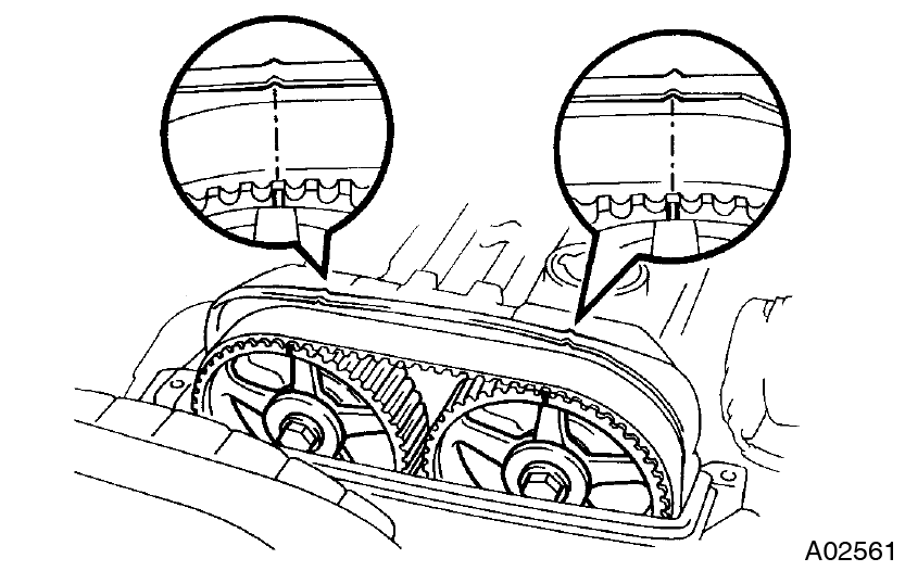
-
Turn the crankshaft pulley, and align its groove with timing mark ”O” of the No.1 timing belt cover.
-
Inspect valve clearance
-
Check only those valves indicated in the illustration.
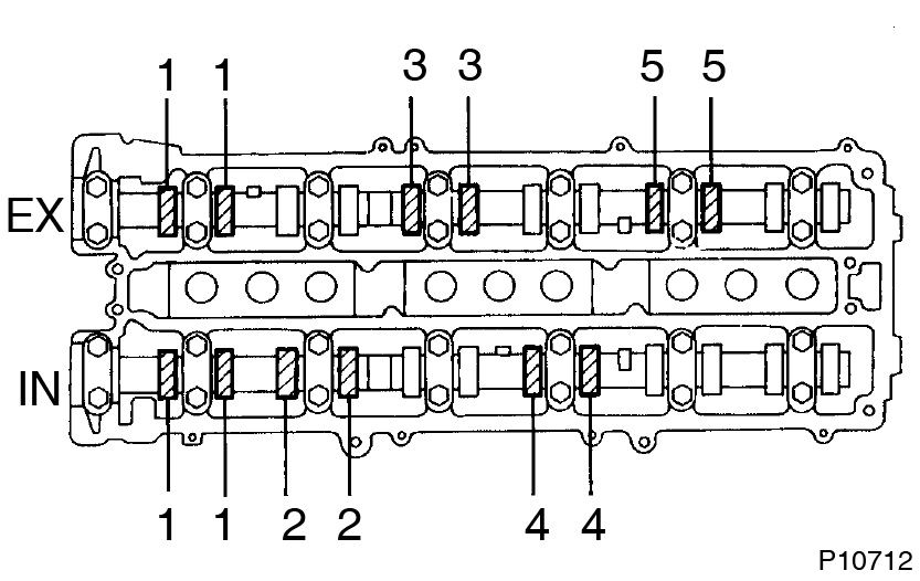
- Using a feeler gauge, measure the clearance between the valve lifter and camshaft.
- Record the valve clearance measurements of those that are out of specification. They will be used later to determine the required replacement adjusting shim.
- Intake 0.15 - 0.25 mm (0.006 - 0.010 in.)
- Exhaust 0.25 - 0.35 mm (0.010 - 0.014 in.)
-
Turn the crankshaft pulley 1 revolution (360°), and align the groove with timing mark ”O” of the No.1 timing belt cover.
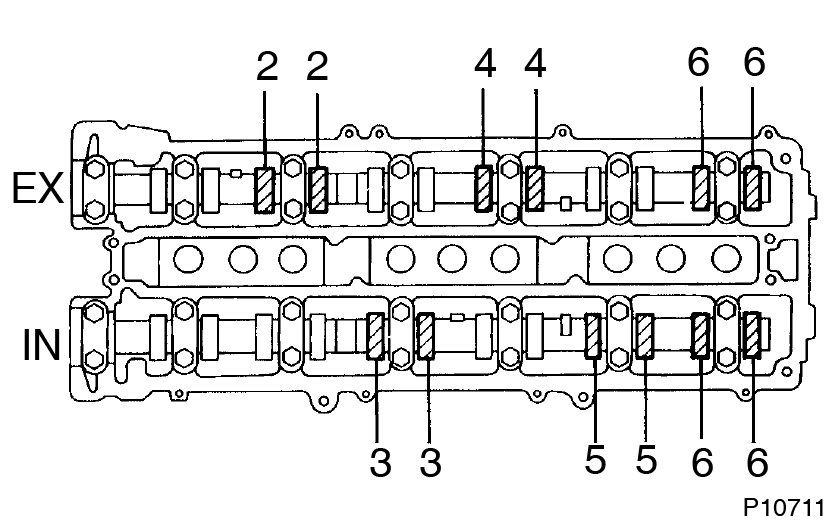
- Check only the valves indicated as shown. Measure the valve clearance. (See procedure in step (a))
-
Check only those valves indicated in the illustration.
-
Adjust valve clearance
-
Remove the adjusting shim.
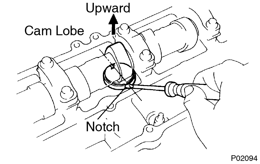
- Turn the camshaft so that the cam lobe for the valve to be adjusted faces up.
- Turn the valve lifter with a screwdriver so that the notches are perpendicular to the camshaft.
-
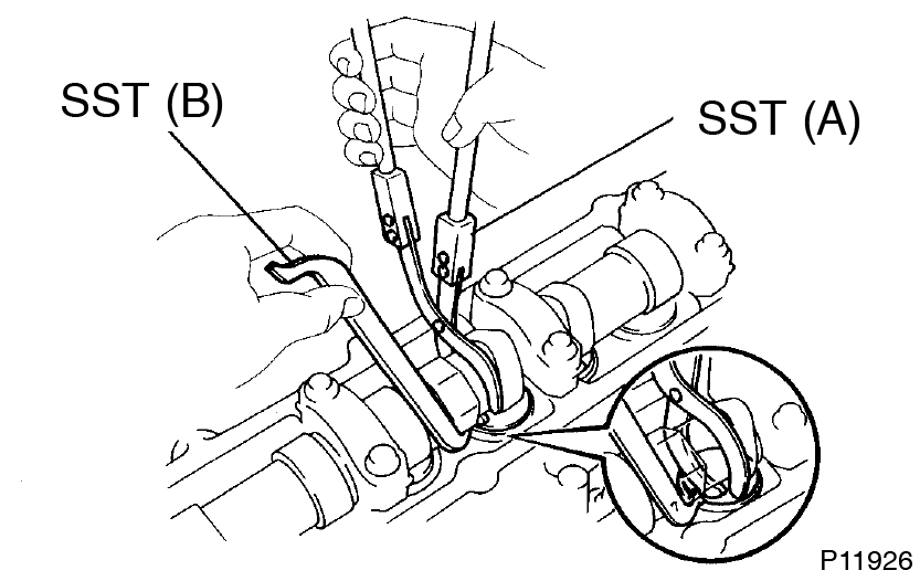
Using SST (A), hold the camshaft as shown in the illustration.
SST 09248–55040 (09248–05410)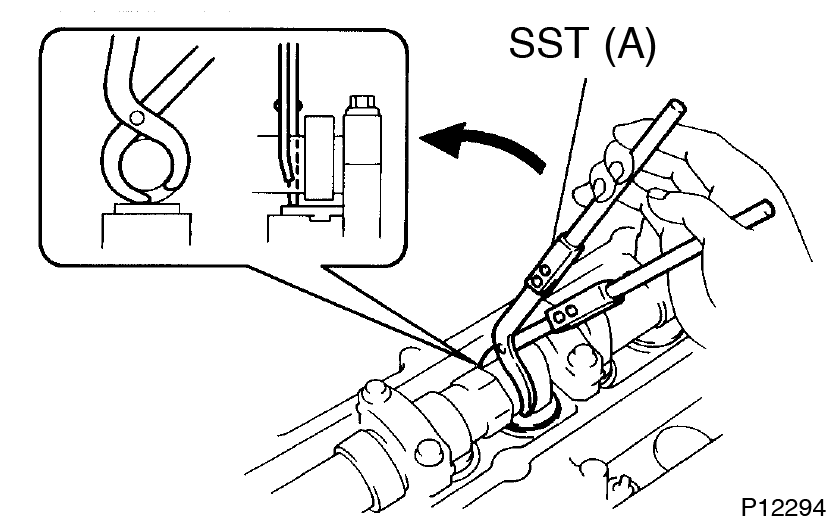
-
Using SST (A), press down the valve lifter and place SST (B) between the camshaft and valve lifter. Remove SST (A).
SST 09248–55040 (09248–05410, 09248–05420)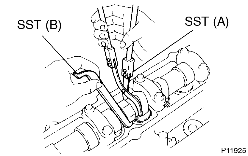
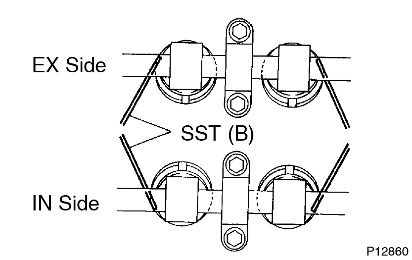
- Apply SST (B) at slight angle on the side marked with ”7”, at the position shown in the illustration.
-
Insert SST (B) gently from the inside as shown in the illustration.
-
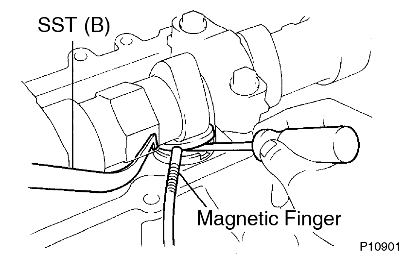
Using a small screwdriver and a magnetic finger, remove the adjusting shim.
-
Determine the replacement adjusting shim size according to the following Formula or Charts:
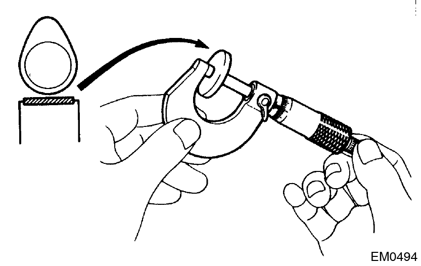
- Using a micrometer, measure the thickness of the removed shim.
-
Calculate the thickness of a new shim so the valve clearance comes within specified value.
T ......... Thickness of used shim
A ......... Measured valve clearance
N ......... Thickness of new shim
Intake
N = T + (A - 0.20 mm (0.008 in.))
Exhaust
N = T + (A - 0.30 mm (0.012 in.)) - Select a new shim with a thickness as close as possible to the calculated values.
Shims are available in 17 sizes in increments of 0.050 mm (0.0020 in.), from 2.500 mm (0.0984 in.) to 3.300 mm (0.1299 in.). -
Install a new adjusting shim.
- Place a new adjusting shim on the valve lifter, with imprinted numbers facing down.
-
Press down the valve lifter with SST (A), and remove SST (B).
SST 09248–55040
- Recheck the valve clearance.
-
Remove the adjusting shim.
-
Reinstall No.1 and No.2 cylinder head covers
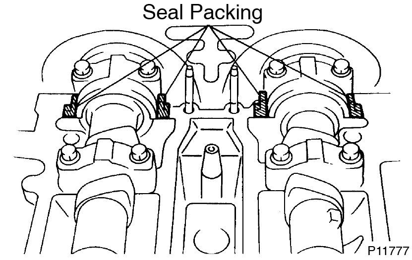
- Remove any old packing (FIPG) material.
-
Apply seal packing to the cylinder head as shown in the illustration.
Seal packing:
Part No. 08826-00080 or equivalent - Install the gaskets to the No.1 and No.2 cylinder head covers.
- Install the 12 seal washers to the bolts.
-
Install the No.2 cylinder head cover with the 6 bolts, 4 seal washers and 4 nuts..
Torque: 5.4 N·m (55 kgf·cm, 48 in.·lbf) -
Install the No.1 cylinder head cover with the 6 bolts, 4 seal washers and 4 nuts..
Torque: 5.4 N·m (55 kgf·cm, 48 in.·lbf) - Connect the 2 PCV hoses to the cylinder head covers.
- Install the bolt holding the VSV to the turbo outlet duct.
- Connect the cruise control actuator cable to the cable bracket.
- Reconnect engine wire protector to No.4 timing belt cover
- Reinstall IAC valve pipe
- Reconnect engine wire protector to cowl top panel
- Reinstall ignition coils assemblies (See page IG-7 )
Adjusting Shim Selection Chart (Intake)
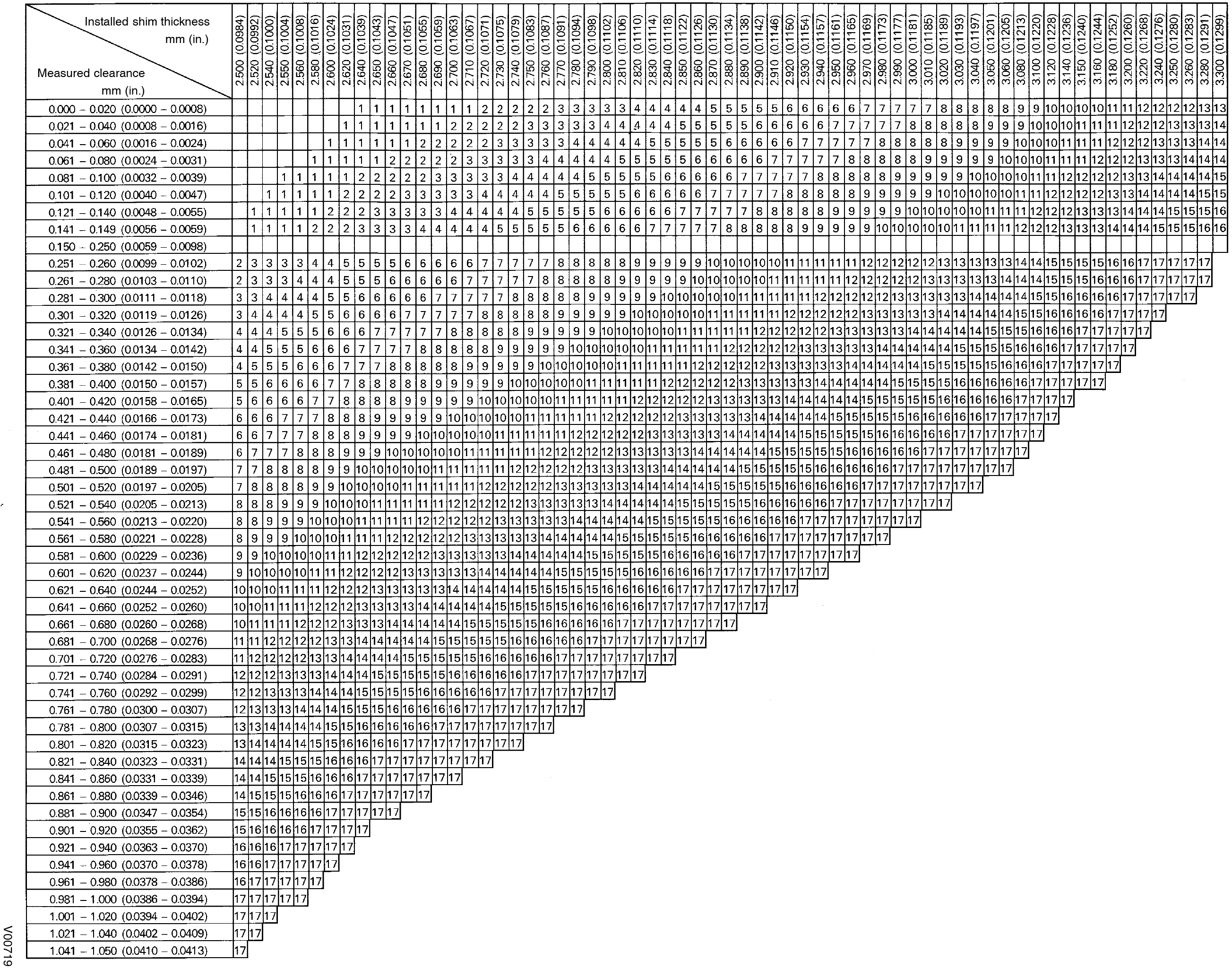 Intake valve clearance (Cold):
0.15 - 0.25 mm (0.006 - 0.010 in.)
The 2.800 mm (0.1102 in.) shim is installed, and the measured clearance is 0.450 mm (0.0177 in.)
Replace the 2.800 mm (0.1102 in.) shim with a new No.12 shim.
Replace the 2.800 mm (0.1102 in.) shim with a new No.12 shim.
| New shim thickness | mm (in.) |
|
Shim
No. |
Thickness |
| 1 | 2.500 (0.0984) |
| 2 | 2.550 (0.1004) |
| 3 | 2.600 (0.1024) |
| 4 | 2.650 (0.1043) |
| 5 | 2.700 (0.1063) |
| 6 | 2.750 (0.1083) |
| 7 | 2.800 (0.1102) |
| 8 | 2.850 (0.1122) |
| 9 | 2.900 (0.1142) |
| 10 | 2.950 (0.1161) |
| 11 | 3.000 (0.1181) |
| 12 | 3.050 (0.1201) |
| 13 | 3.100 (0.1220) |
| 14 | 3.150 (0.1240) |
| 15 | 3.200 (0.1260) |
| 16 | 3.250 (0.1280) |
| 17 | 3.300 (0.1299) |
New shims have the thickness in millimeters imprinted on the face.
Adjusting Shim Selection Chart (Exhaust)
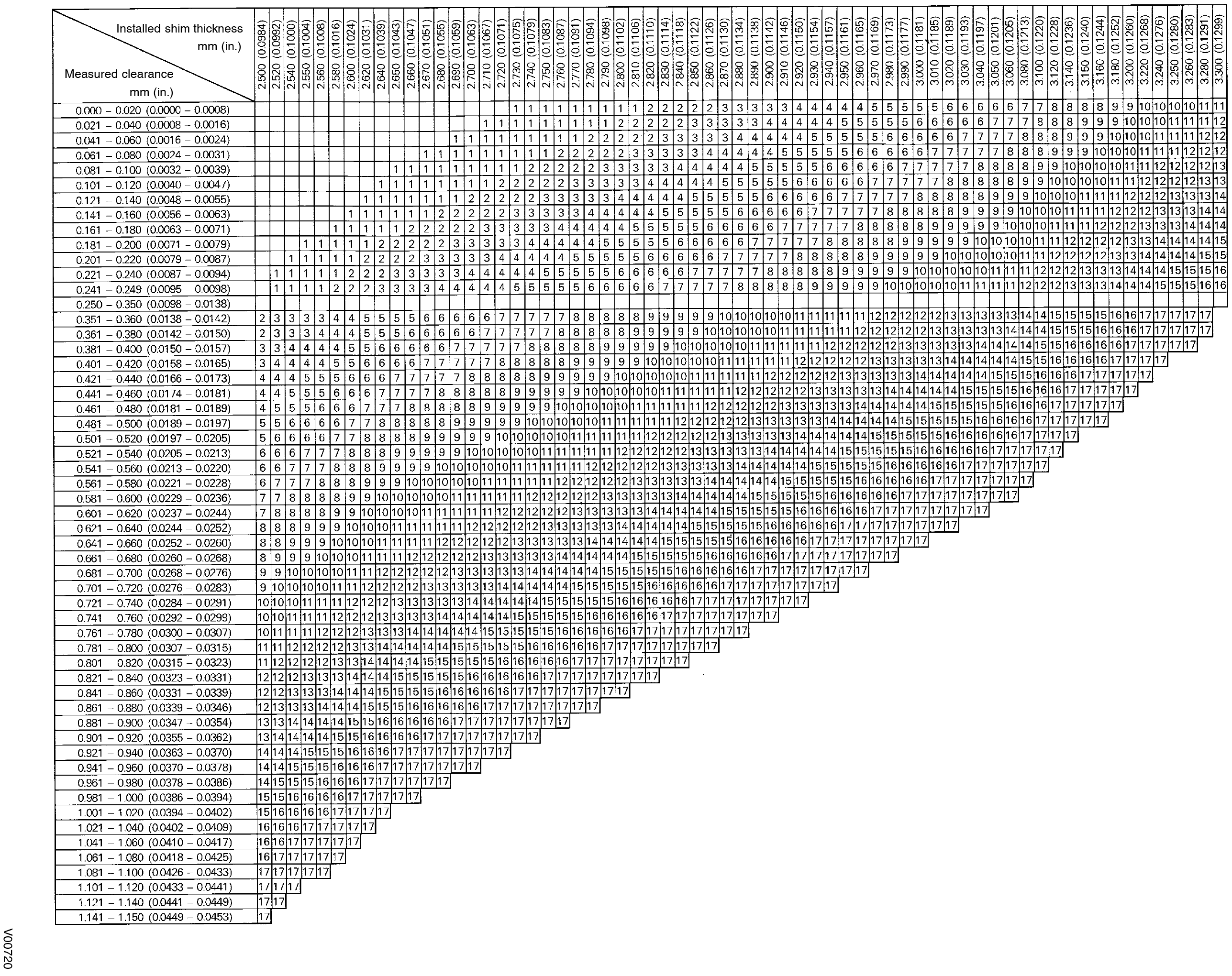 Exhaust valve clearance (Cold):
0.25 - 0.35 mm (0.010 - 0.014 in.)
The 2.800 mm (0.1102 in.) shim is installed, and the measured clearance is 0.450 mm (0.0177 in.)
Replace the 2.800 mm (0.1102 in.) shim with a new No.10 shim.
Replace the 2.800 mm (0.1102 in.) shim with a new No.10 shim.
| New shim thickness | mm (in.) |
|
Shim
No. |
Thickness |
| 1 | 2.500 (0.0984) |
| 2 | 2.550 (0.1004) |
| 3 | 2.600 (0.1024) |
| 4 | 2.650 (0.1043) |
| 5 | 2.700 (0.1063) |
| 6 | 2.750 (0.1083) |
| 7 | 2.800 (0.1102) |
| 8 | 2.850 (0.1122) |
| 9 | 2.900 (0.1142) |
| 10 | 2.950 (0.1161) |
| 11 | 3.000 (0.1181) |
| 12 | 3.050 (0.1201) |
| 13 | 3.100 (0.1220) |
| 14 | 3.150 (0.1240) |
| 15 | 3.200 (0.1260) |
| 16 | 3.250 (0.1280) |
| 17 | 3.300 (0.1299) |
New shims have the thickness in millimeters imprinted on the face.
This guide is based on the book edition Toyota (RM502U, 1997)
Volksbibliothek, info@volksbibliothek.com
Back Next