Circuit inspection
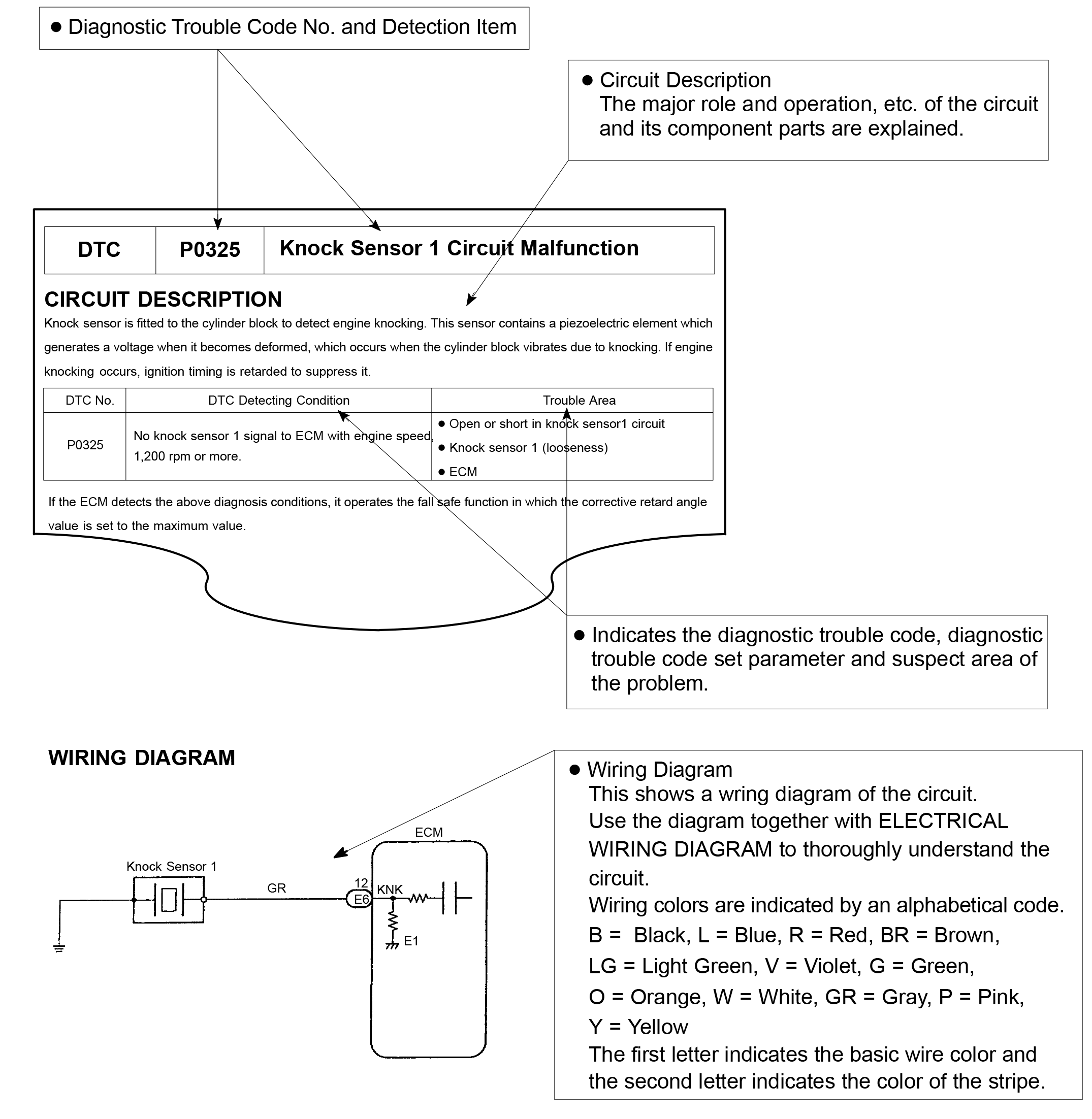
How to read and use each page is shown below

- Indicates the place to check the voltage or resistance.
- Indicates the connector position to checked, from the front or back side.
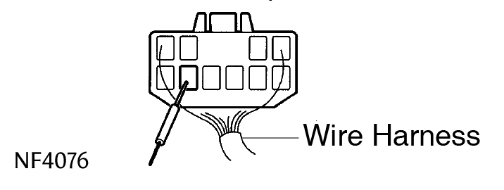
Check from the connector back side. (with harness)
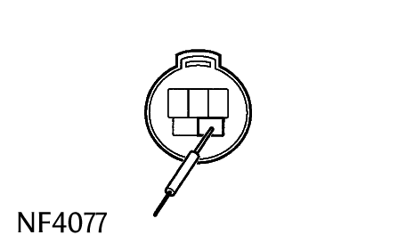
Check from the connector front side. (without harness)
In this case, care must be taken not to bend the terminals.
- Indicates the condition of the connector of ECU during the check.


This guide is based on the book edition Toyota (RM502U, 1997)
Volksbibliothek, info@volksbibliothek.com
Back Next