Cylinder head inspection
-
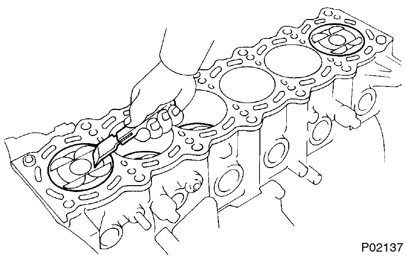
Clean top surfaces of pistons and cylinder block
-
Turn the crankshaft, and bring each piston to top dead center (TDC). Using a gasket scraper, remove all the carbon from the piston top surface.
-
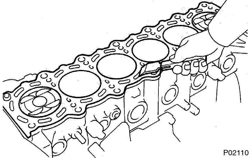
Using a gasket scraper, remove all the gasket material from the top surface of the cylinder block.
-
Using compressed air, blow carbon and oil from the bolt holes.
Protect your eyes when using high pressure-compressed air.
-
Turn the crankshaft, and bring each piston to top dead center (TDC). Using a gasket scraper, remove all the carbon from the piston top surface.
-
Remove gasket material
Using a gasket scraper, remove all the gasket material from the cylinder block surface.Be careful not to scratch the cylinder block contact surface.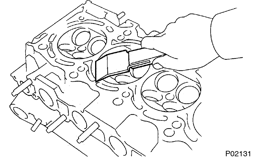
-
Clean combustion chambers
Using a wire brush, remove all the carbon from the combustion chambers.Be careful not to scratch the cylinder block contact surface.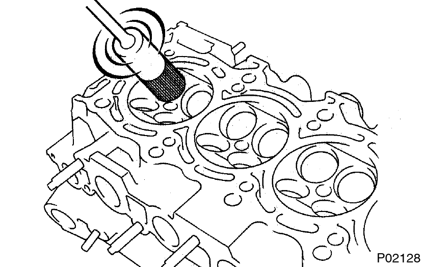
-
Clean valve guide bushings
Using a valve guide bushing brush and solvent, clean all the guide bushings.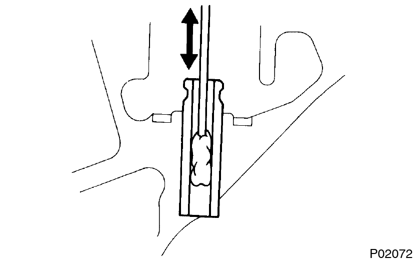
-
Clean cylinder head
Using a soft brush and solvent, thoroughly clean the cylinder head.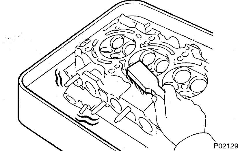
-
Inspect for flatness
Using precision straight edge and feeler gauge, measure the surfaces contacting the cylinder block, intake and exhaust manifolds for warpage.
Maximum warpage: 0.10 mm (0.0039 in.)
If warpage is greater than maximum, replace the cylinder head.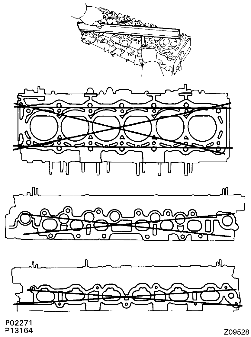
-
Inspect for cracks
Using a dye penetrant, check the combustion chamber, intake ports, exhaust ports and cylinder block surface for cracks.
If cracked, replace the cylinder head.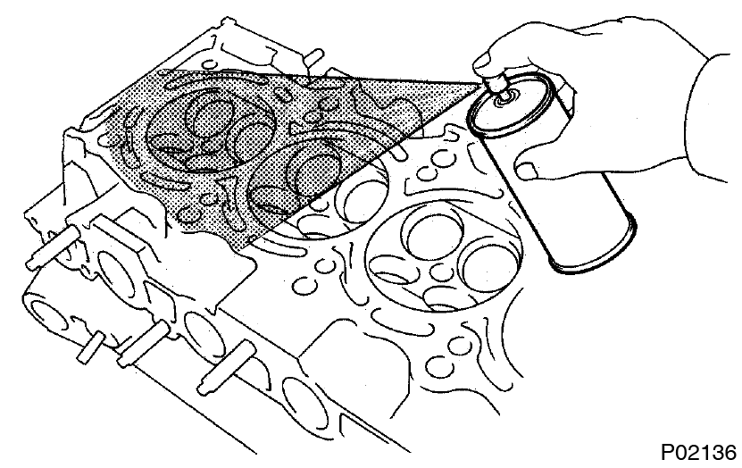
-
Clean valves
-
Using a gasket scraper, chip off any carbon from the valve head.
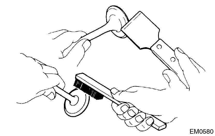
- Using a wire brush, thoroughly clean the valve.
-
Using a gasket scraper, chip off any carbon from the valve head.
-
Inspect valve stems and guide bushings
-
Using a caliper gauge, measure the inside diameter of the guide bushing.
Bushing inside diameter:
6.010 - 6.030 mm (0.2366 - 0.2374 in.)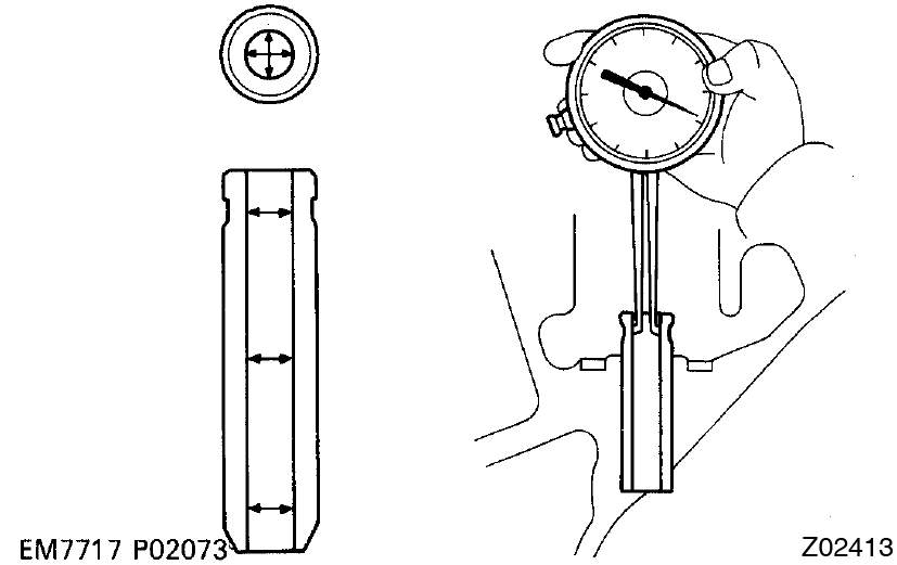
-
Using a micrometer, measure the diameter of the valve stem.
Valve stem diameter:
Intake 5.970 - 5.985 mm (0.2350 - 0.2356 in.)
Exhaust 5.965 - 5.980 mm (0.2348 - 0.2354 in.)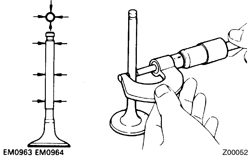
-
Subtract the valve stem diameter measurement from the guide bushing inside diameter measurement.
Standard oil clearance:
Intake 0.025 - 0.060 mm (0.0010 - 0.0024 in.)
Exhaust 0.030 - 0.065 mm (0.0012 - 0.0026 in.)
Maximum oil clearance:
Intake 0.08 mm (0.0031 in.)
Exhaust 0.10 mm (0.0039 in.)
-
Using a caliper gauge, measure the inside diameter of the guide bushing.
-
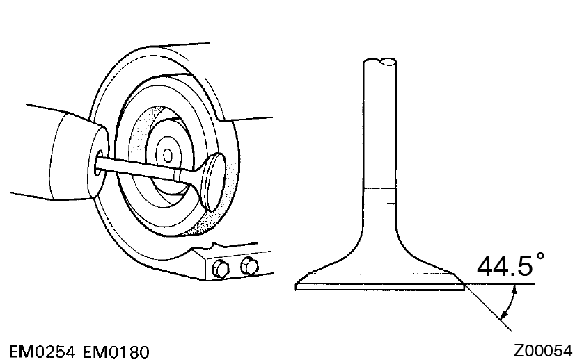
Inspect and grind valves
-
Grind the valve enough to remove pits and carbon.
-
Check that the valve is ground to the correct valve face angle.
Valve face angle: 44.5° -
Check the valve head margin thickness
Standard margin thickness:
0.8 - 1.2 mm (0.031 - 0.047 in.)
Minimum margin thickness:
0.5 mm (0.020 in.)
If the margin thickness is less than minimum, replace the valve.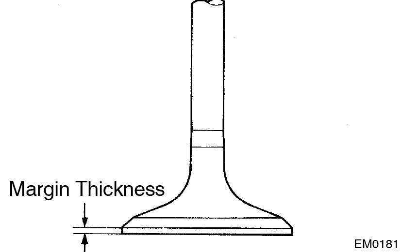
-
Check the valve overall length.
Standard overall length:
Intake 98.29 - 98.79 mm (3.8697 - 3.8894 in.)
Exhaust 98.84 - 99.34 mm (3.8913 - 3.9110 in.)
Minimum overall length:
Intake 98.19 mm (3.8657 in.)
Exhaust 98.74 mm (3.8874 in.)
If the overall length is less than minimum, replace the valve.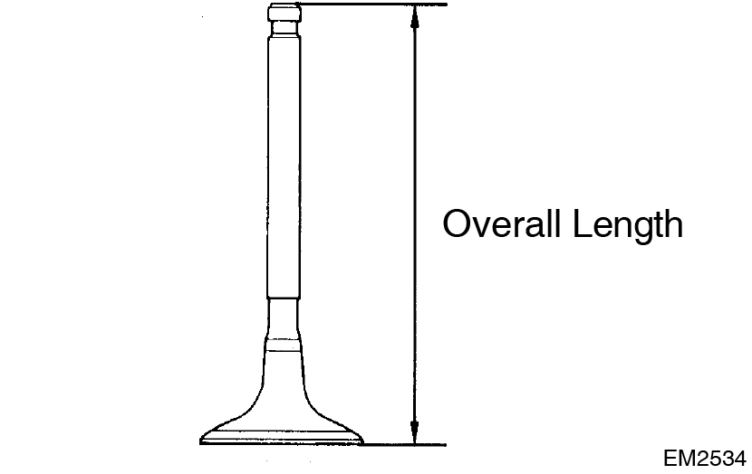
-
Check the surface of the valve stem tip for wear.
If the valve stem tip is worn, resurface the tip with a grinder or replace the valve.Do not grind off more than the minimum overall length.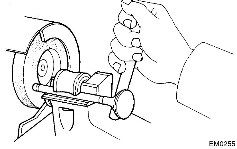
-
Grind the valve enough to remove pits and carbon.
-
Inspect and clean valve seats
-
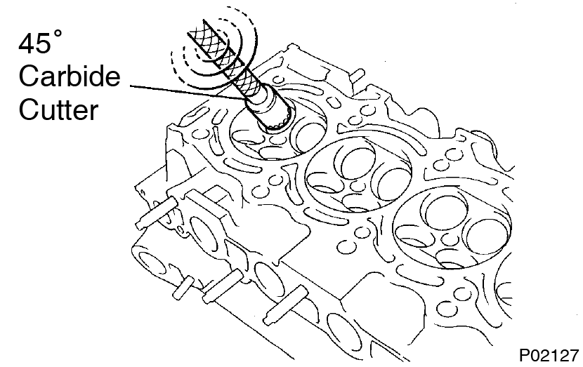
Using a 45° carbide cutter, resurface the valve seats. Remove only enough metal to clean the seats.
-
Check the valve seating position.
Apply a thin coat of prussian blue (or white lead) to the valve face. Lightly press the valve against the seat. Do not rotate the valve.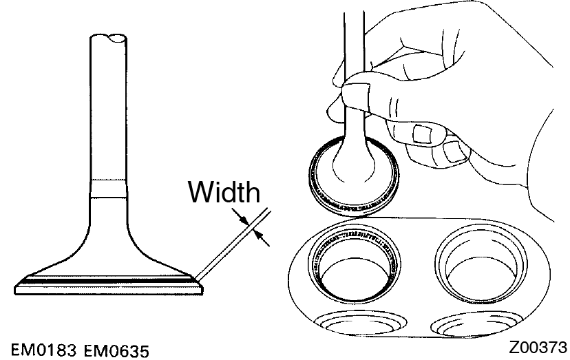
-
Check the valve face and seat for the following:
- If blue appears 360° around the face, the valve is concentric. If not, replace the valve.
- If blue appears 360° around the valve seat, the guide and face are concentric. If not, resurface the seat.
-
Check that the seat contact is in the middle of the valve face with the following width:
Intake 1.0 - 1.4 mm (0.039 - 0.055 in.)
Exhaust 1.2 - 1.6 mm (0.047 - 0.063 in.)
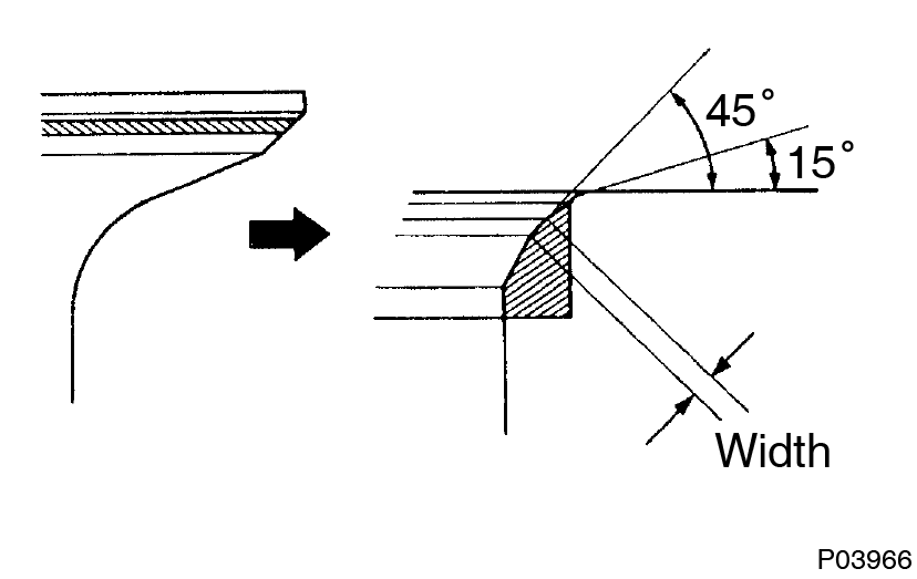
If not, correct the valve seats as follows: -
If the seating is too high on the valve face, use 15° and 45° cutters to correct the seat.
-
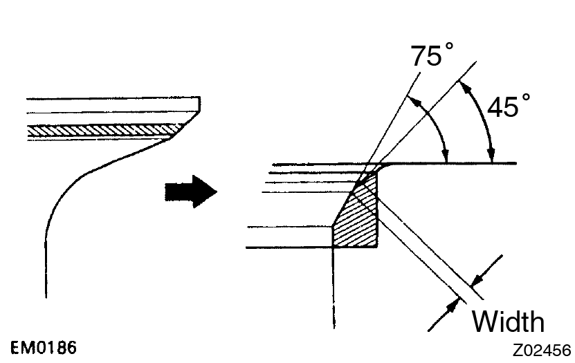
If the seating is too low on the valve face, use 75° and 45° cutters to correct the seat.
-
Hand-lap the valve and valve seat with an abrasive compound.
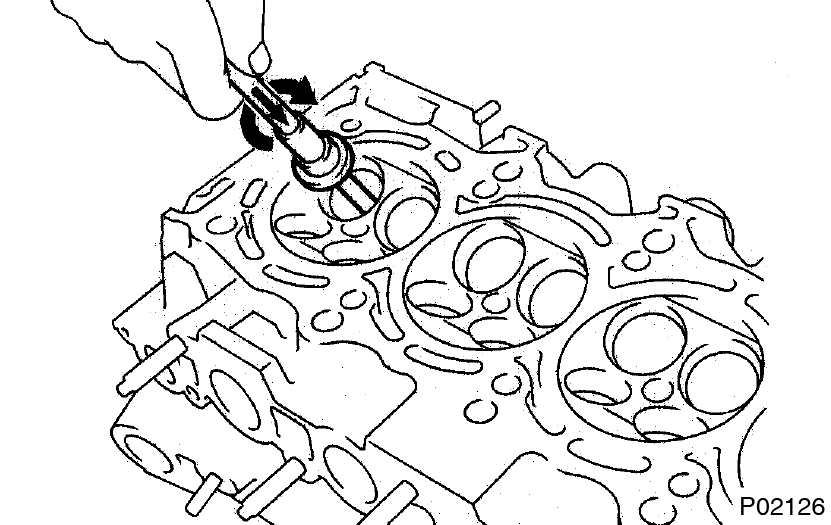
- After hand-lapping, clean the valve and valve seat.
-
Using a 45° carbide cutter, resurface the valve seats. Remove only enough metal to clean the seats.
-
Inspect valve springs
-
Using a steel square, measure the deviation of the valve spring.
Maximum deviation: 2.0 mm (0.079 in.)
If deviation is greater than maximum, replace the valve spring.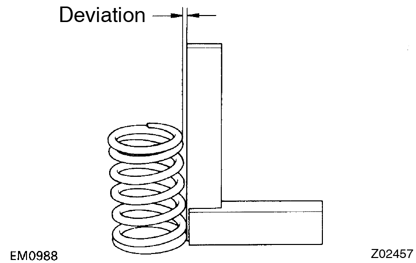
-
Using vernier calipers, measure the free length of the valve spring.
Free length: 41.70 mm (1.6417 in.)
If the free length is not as specified, replace the valve spring.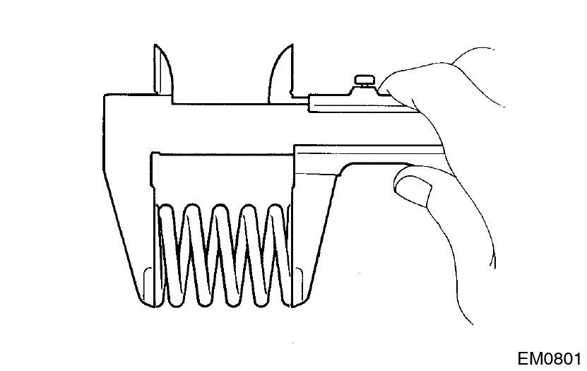
-
Using a spring tester, measure the tension of the valve spring at the specified installed length.
Installed tension:
186 - 206 N (19.0 - 21.0 kgf, 42 - 46 lbf)
at 34.5 mm (1.358 in.)
If the installed tension is not as specified, replace the valve spring.
-
Using a steel square, measure the deviation of the valve spring.
-
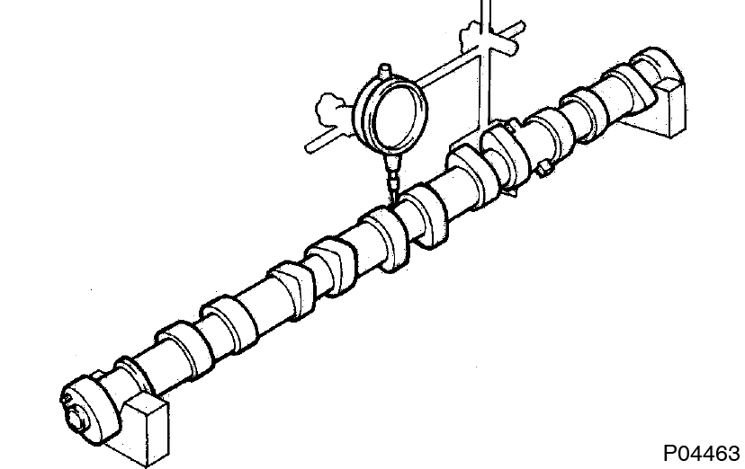
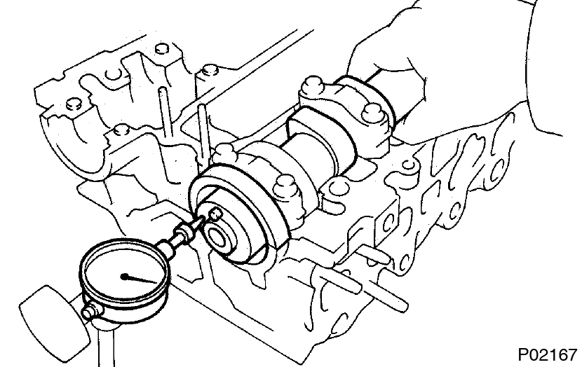
Inspect camshaft for runout
-
Place the camshaft on V-blocks.
-
Using a dial indicator, measure the circle runout at the center journal.
Maximum circle runout: 0.08 mm (0.0031 in.)
If the circle runout is greater than maximum, replace the camshaft.
-
Place the camshaft on V-blocks.
-
Inspect cam lobes
Using a micrometer, measure the cam lobe height.
Standard cam lobe height:
Intake 44.570 - 44.670 mm (1.7547 - 1.7587 in.)
Exhaust 44.770 - 44.870 mm (1.7626 - 1.7665 in.)
Maximum cam lobe height:
Intake 44.42 mm (1.7488 in.)
Exhaust 44.62 mm (1.7567 in.)
If the cam lobe height is less than minimum, replace the camshaft.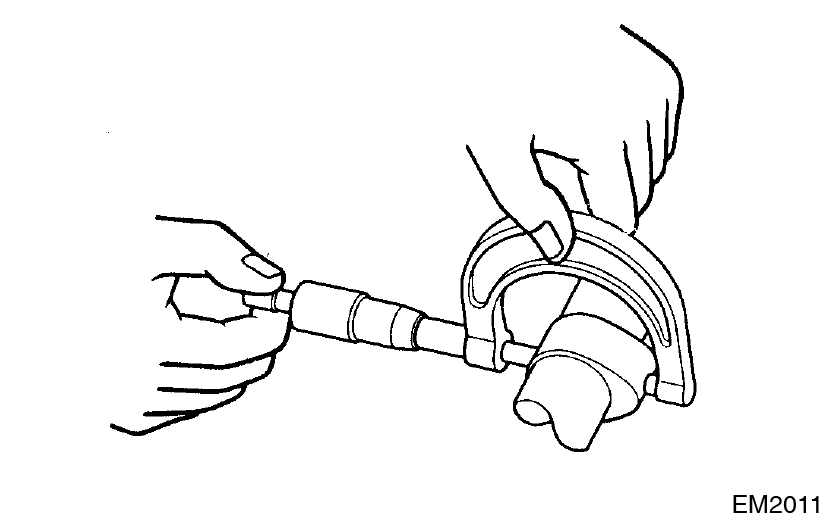
-
Inspect camshaft journals
Using a micrometer, measure the journal diameter.
Journal diameter:
28.949 - 28.965 mm (1.1397 - 1.1404 in.)
If the journal diameter is not as specified, check the oil clearance.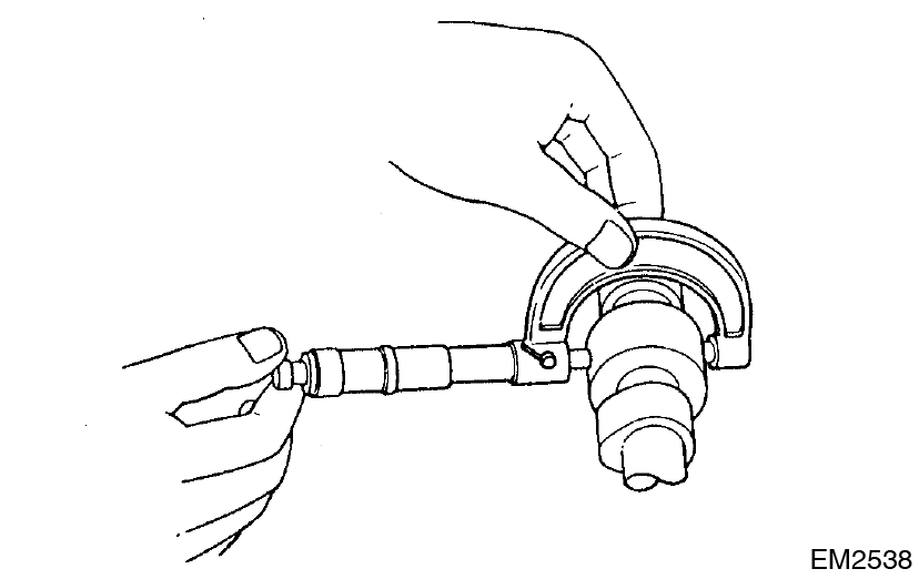
-
Inspect camshaft bearings
Check the bearings for flaking and scoring.
If the bearings are damaged, replace the bearing caps and cylinder head as a set.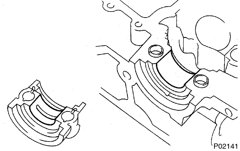
-
Inspect camshaft journal oil clearance
-
Clean the bearing caps and camshaft journals.
- Place the camshafts on the cylinder head.
- Lay a strip of Plastigage across each of the camshaft journals.
-
Install the bearing caps (See page EM-47 ).
Torque: 20 N·m (200 kgf·cm, 14 ft·lbf)Do not turn the camshaft.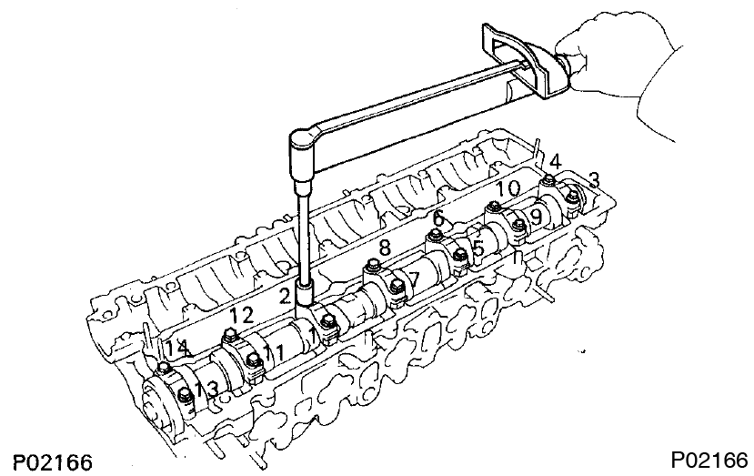
- Remove the bearing caps.
-
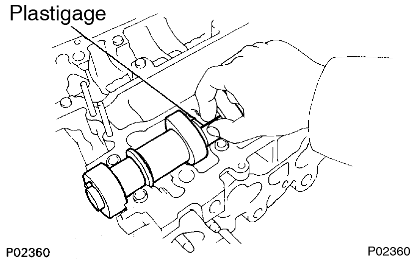
Measure the Plastigage at its widest point.
Standard oil clearance:
0.035 - 0.072 mm (0.0014 - 0.0028 in.)
Maximum oil clearance:
0.10 mm (0.0039 in.)
If the oil clearance is greater than maximum, replace the camshaft. If necessary, replace the bearing caps and cylinder head as a set.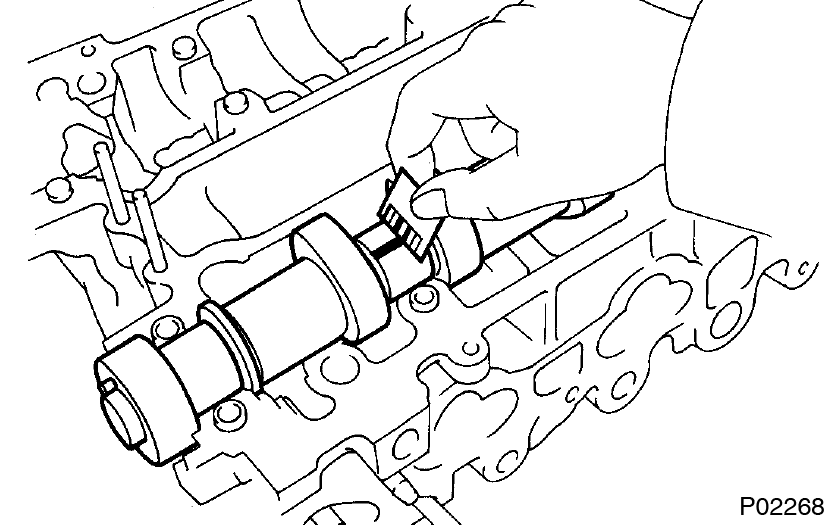
- Completely remove the Plastigage.
-
Clean the bearing caps and camshaft journals.
-
Inspect camshaft thrust clearance
-
Install the camshafts (See page EM-47 )
-
Using a dial indicator, measure the thrust clearance while moving the camshaft back and forth.
Standard thrust clearance:
0.080 - 0.190 mm (0.0031 - 0.0075 in.)
Maximum thrust clearance:
0.30 mm (0.0118 in.)
If the thrust clearance is greater than maximum, replace the camshaft. If necessary, replace the bearing caps and cylinder head as a set.
-
Install the camshafts (See page EM-47 )
-
Inspect valve lifters and lifter bores
-
Using a caliper gauge, measure the lifter bore diameter of the cylinder head.
Lifter bore diameter:
31.000 - 31.016 mm (1.2205 - 1.2211 in.)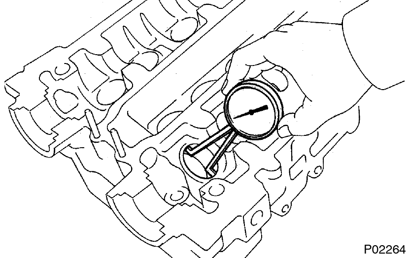
-
Using a micrometer, measure the lifter diameter.
Lifter diameter:
30.966 - 30.976 mm (1.2191 - 1.2195 in.)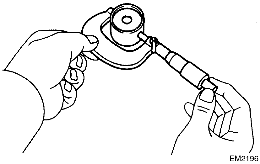
-
Subtract the lifter diameter measurement from the lifter bore diameter measurement.
Standard oil clearance:
0.024 - 0.050 mm (0.0009 - 0.0020 in.)
Maximum oil clearance:
0.07 mm (0.0028 in.)
If the oil clearance is greater than maximum, replace the lifter.
If necessary, replace the cylinder head.
-
Using a caliper gauge, measure the lifter bore diameter of the cylinder head.
-
Inspect air intake chamber
Using a precision straight edge and feeler gauge, measure the surfaces contacting the intake manifold for warpage.
Maximum warpage: 0.15 mm (0.0059 in.)
If warpage is greater than maximum, replace the chamber.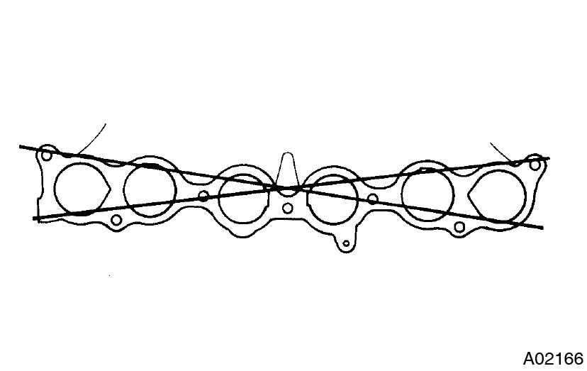
-
Inspect intake manifold
Using a precision straight edge and feeler gauge, measure the surfaces contacting the cylinder head and air intake chamber for warpage.
Maximum warpage: 0.15 mm (0.0059 in.)
If warpage is greater than maximum, replace the manifold.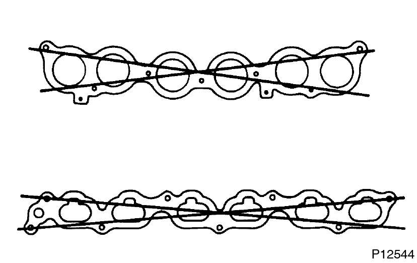
-
Inspect exhaust manifold
Using a precision straight edge and feeler gauge, measure the surfaces contacting the cylinder head for warpage.
Maximum warpage: 0.80 mm (0.0315 in.)
If warpage is greater than maximum, replace the manifold.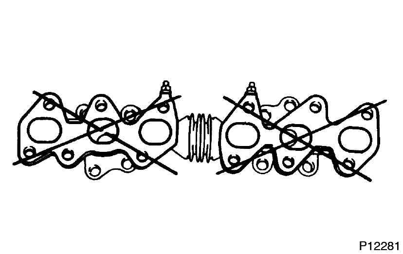
-
Inspect cylinder head bolts
Using a vernier caliper, measure the thread outside diameter of the bolt.
Standard outside diameter:
10.8 - 11.0 mm (0.425 - 0.433 in.)
Minimum outside diameter: 10.7 mm (0.421 in.)
If the diameter is less than minimum, replace the bolt.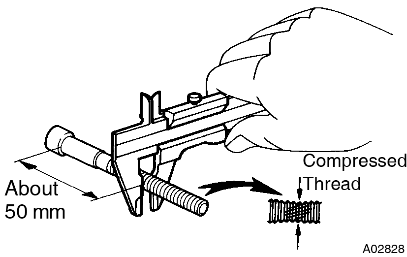
This guide is based on the book edition Toyota (RM502U, 1997)
Volksbibliothek, info@volksbibliothek.com
Back Next