Cylinder block disassembly
-
M/T:
Remove flywheel -
A/T:
Remove drive plate - Install engine to engine stand for disassembly
- Remove generator
- Remove timing belt and pulleys (See page EM-15 )
-
Remove cylinder head (See page EM-29 )
- Remove oil cooler (See page LU-20 )
-
Remove No.2 water bypass pipe with hose
Remove the 2 bolts, 2 nuts, water bypass pipe and gasket. -
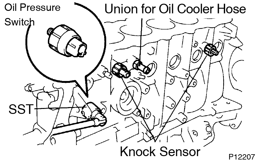
Remove knock sensors
Using SST, remove the switch and sensors.
SST 09816-30010 -
Remove oil filter bracket
Remove the union bolt, gasket, oil filter bracket and O-ring. - Remove LH engine mounting bracket and insulator assembly
- Remove fuel pipe support
-
Remove oil pressure switch and knock sensors
-
Using SST, remove the switch and sensors.
SST 09816-30010 - Remove the union nut and gasket.
-
Using SST, remove the switch and sensors.
- Remove union for oil cooler hose
- Remove engine coolant drain plug
-
Remove RH engine mounting bracket and insulator assembly
- Remove crankshaft position sensor
- Remove water pump (See page CO-7 )
- Remove oil pump (See page LU-9 )
-
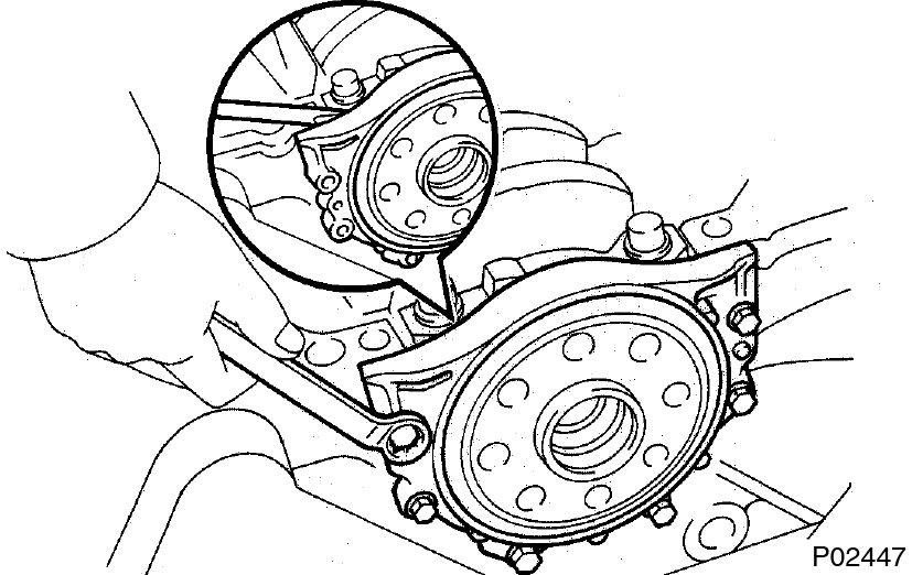
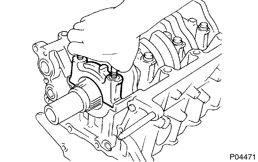
Remove rear oil seal retainer
- Remove the 6 bolts.
- Remove the oil seal retainer by prying the area between the oil seal retainer and main bearing cap with a screwdriver.
-
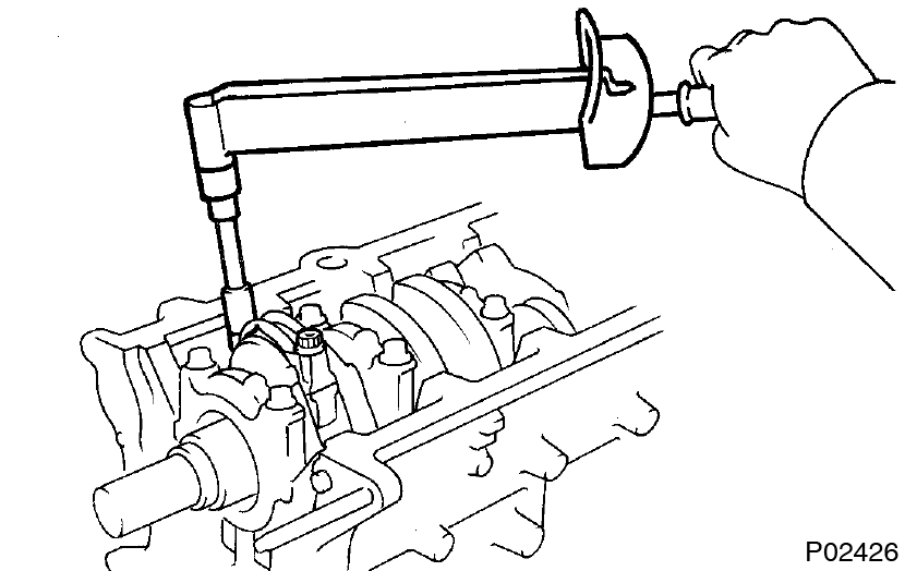
Check connecting rod thrust clearance
 Using a dial indicator, measure the thrust clearance while moving the connecting rods back and forth.
Standard thrust clearance:
0.250 - 0.402 mm (0.0098 - 0.0158 in.)
Maximum thrust clearance:
0.50 mm (0.0197 in.)
If the thrust clearance is greater than maximum, replace the connecting rod assembly(s). If necessary, replace the crankshaft.
Connecting rod thickness:
25.898 - 25.950 mm (1.0196 - 1.0217 in.) -
Remove connecting ROD caps and check oil clearance
-
Check the matchmarks on the connecting rod and cap to ensure correct reassembly.
-
Remove the connecting rod cap bolts.
-
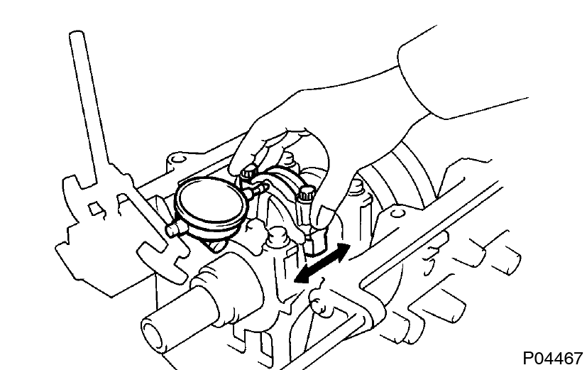
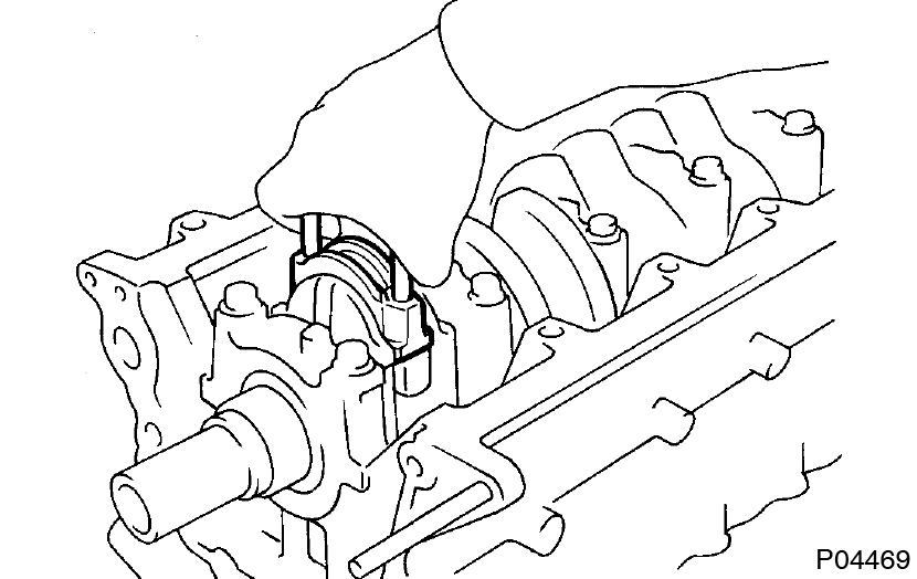
Using the 2 removed connecting rod bolts, remove the connecting rod cap and lower bearing by wiggling the connecting rod cap right and left.
Keep the lower bearing inserted with the connecting rod cap.
- Clean the crank pin and bearings.
-
Check the crank pin and bearing for pitting and scratches.
If the crank pin or bearing is damaged, replace the bearings. If necessary, replace the crankshaft. -
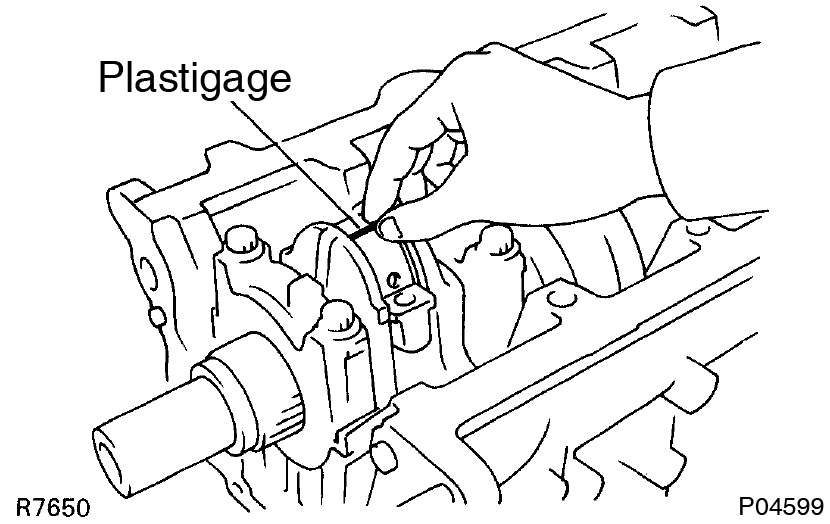
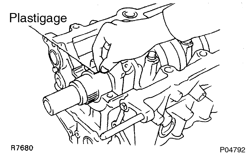
Lay a strip of Plastigage across the crank pin.
-
Install the connecting rod cap with the 2 bolts. (See page EM-88 )
 1st 29 N·m (300 kgf·cm, 22 ft·lbf)
2nd Turn extra 90°Do not turn the crankshaft. - Remove the 2 bolts, connecting rod cap and lower bearing. (See procedure step (b) and (c))
-
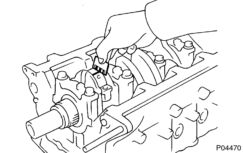
Measure the Plastigage at its widest point.
 Standard oil clearance:
STD 0.023 - 0.041 mm (0.0009 - 0.0016 in.)
U/S 0.25 0.028 - 0.066 mm (0.0011 - 0.0026 in.)
Maximum oil clearance. STD 0.07 mm (0.0027 in.)
U/S 0.25 0.08 mm (0.0031 in.)
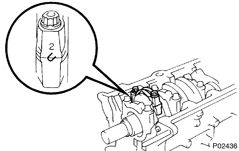
If the oil clearance is greater than maximum, replace the bearings. If necessary, grind or replace the crankshaft.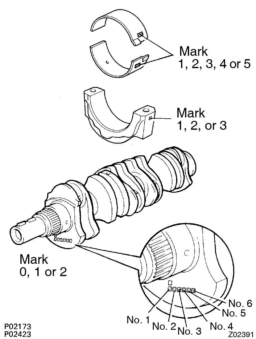 If using a standard bearing, replace with one having the same number. If the number of the bearing cannot be determined, select the correct bearing by adding together the numbers imprinted on the connecting rod cap and crankshaft, then selecting the bearing with the same number as the total. There are 5 sizes of standard bearings, marked ”1”, ”2”, ”3”, ”4” and ”5” accordingly.
Example:
If using a standard bearing, replace with one having the same number. If the number of the bearing cannot be determined, select the correct bearing by adding together the numbers imprinted on the connecting rod cap and crankshaft, then selecting the bearing with the same number as the total. There are 5 sizes of standard bearings, marked ”1”, ”2”, ”3”, ”4” and ”5” accordingly.
Example:Number mark Connecting rod cap 1 2 3 Crankshaft 0 1 2 0 1 2 0 1 2 Use bearing 1 2 3 2 3 4 3 4 5
Connecting rod cap ”3” +Crankshaft ”1” = Total number 4 (Use bearing ”4”)
Reference:
Connecting rod big end inside diameter:
Crankshaft crank pin diameter:Mark ”1” 55.025 - 55.031 mm (2.1663 - 2.1666 in.) Mark ”2” 55.031 - 55.037 mm (2.1666 - 2.1668 in.) Mark ”3” 55.037 - 55.043 mm (2.1668 - 2.1670 in.)
Bearing center wall thickness:Mark ”0” 51.994 - 52.000 mm (2.0470 - 2.0472 in.) Mark ”1” 51.988 - 51.994 mm (2.0468 - 2.0470 in.) Mark ”2” 51.982 - 51.988 mm (2.0465 - 2.0468 in.) Mark ”1” 1.498 - 1.501 mm (0.0590 - 0.0591 in.) Mark ”2” 1.501 - 1.504 mm (0.0591 - 0.0592 in.) Mark ”3” 1.504 - 1.507 mm (0.0592 - 0.0593 in.) Mark ”4” 1.507 - 1.510 mm (0.0593 - 0.0594 in.) Mark ”5” 1.510 - 1.513 mm (0.0594 - 0.0596 in.) - Completely remove the Plastigage.
-
Check the matchmarks on the connecting rod and cap to ensure correct reassembly.
-
Remove piston and connecting ROD assemblies
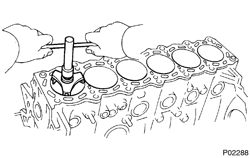
- Using a ridge reamer, remove all the carbon from the top of the cylinder.
- Push the piston, connecting rod assembly and upper bearing through the top of the cylinder block.
- Keep the bearings, connecting rod and cap together.
- Arrange the piston and connecting rod assemblies in correct order.
-
Check crankshaft thrust clearance
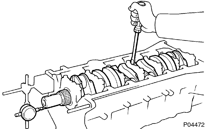 Using a dial indicator, measure the thrust clearance while prying the crankshaft back and forth with a screwdriver.
Standard thrust clearance:
0.020 - 0.220 mm (0.0008 - 0.0087 in.)
Maximum thrust clearance:
0.30 mm (0.0118 in.)
If the thrust clearance is greater than maximum, replace the thrust washers as a set.
Thrust washer thickness:
1.940 - 1.990 mm (0.0764 - 0.0783 in.) -
Remove main bearing caps and check oil clearance
-
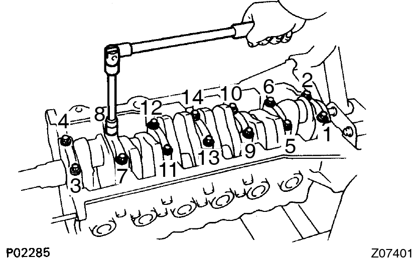
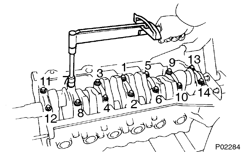
Uniformly loosen and remove the 14 main bearing cap bolts, in several passes, in the sequence shown.
-
Using the removed main bearing cap bolts, pry the main bearing cap back and forth, and remove the main bearing caps, lower bearings and lower thrust washers (No.4 main bearing cap only).
- Keep the lower bearing and main bearing cap together.
- Arrange the main bearing caps and lower thrust washers in correct order.
-
Lift out the crankshaft.
 Keep the upper bearing and upper thrust washers together with the cylinder block.
 - Clean each main journal and bearing.
-
Check each main journal and bearing for pitting and scratches.
If the journal or bearing is damaged, replace the bearings. If necessary, grind or replace the crankshaft. - Place the crankshaft on the cylinder block.
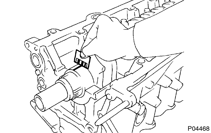
- Lay a strip of Plastigage across each journal.
-
Install the main bearing caps.(See page EM-88 )
Torque:
1st 44 N·m (450 kgf·cm, 33 ft·lbf)
2nd Turn extra 90°Do not turn the crankshaft. -
Remove the main bearing caps.
(See procedure step (a) and (b)) -
Measure the Plastigage at its widest point.
 Standard clearance:
STD 0.026 - 0.040 mm (0.0010 - 0.0016 in.)
U/S 0.25 0.025 - 0.061 mm (0.0010 - 0.0024 in.)
Maximum clearance:
STD 0.06 mm (0.0024 in.)
U/S 0.25: 0.08 mm (0.0031 in.) If the oil clearance is greater than maximum, replace the bearings. If necessary, grind or replace the crankshaft.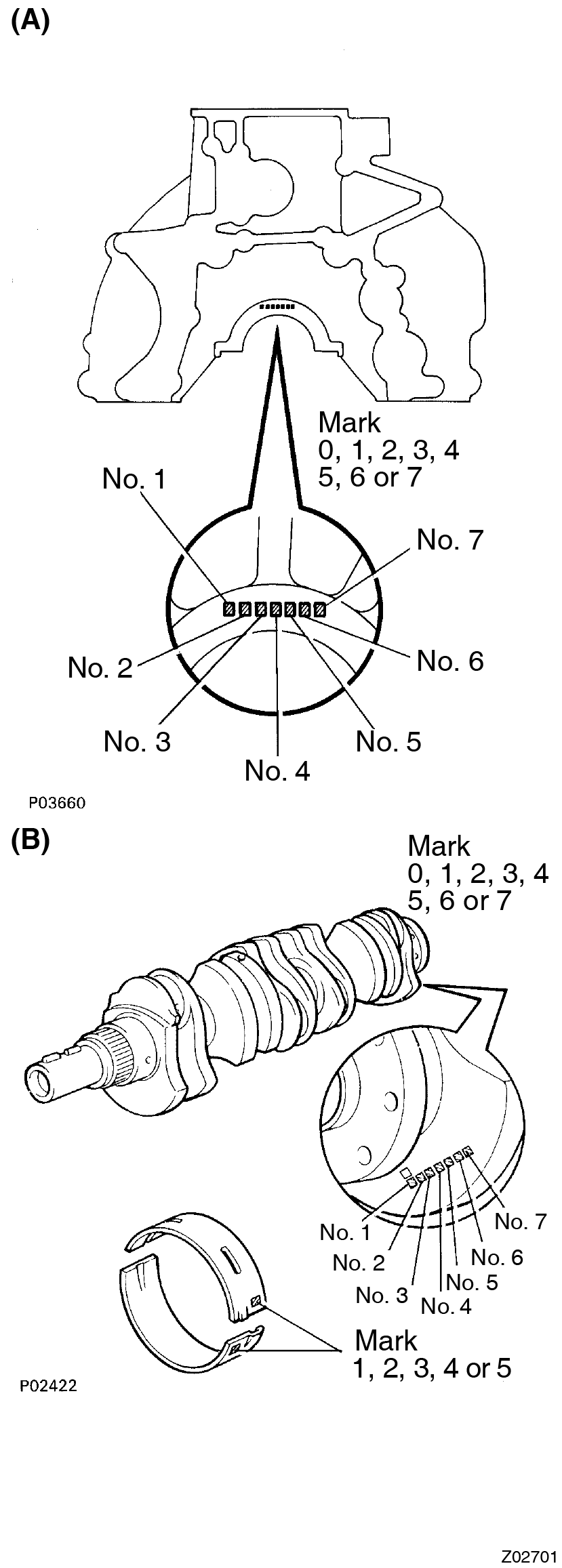 If using a standard bearing, replace with one having the same number. If the number of the bearing cannot be determined, select the correct bearing by adding together the numbers imprinted on the cylinder block and crankshaft, then refer to the table below for the appropriate bearing number. There are 5 sizes of standard bearings, marked ”1”, ”2”, ”3”, ”4” and ”5” accordingly.Standard sized bearing selection chartExample:
Total number ” ”:Number mark Cylinder block (A) + Cankshaft (B) = 0 - 2 3 - 5 6 - 8 9 - 11 12 - 14 Use bearing ”1” ”2” ”3” ”4” ”5”
Cylinder block ”3” (A) + Crankshaft ”4”(B) = Total number 7 (Use bearing ”3”)Example:Crankshaft number mark Cylinder block number mark 0 1 2 3 4 5 6 7 0 1 1 1 2 2 2 3 3 1 1 1 2 2 2 3 3 3 2 1 2 2 2 3 3 3 4 3 2 2 2 3 3 3 4 4 4 2 2 3 3 3 4 4 4 5 2 3 3 3 4 4 5 5 6 3 3 3 4 4 5 5 5 7 3 3 4 4 5 5 5 5
Cylinder block ”3” Crankshaft ”4” = Use bearing ”3”
Reference:
Cylinder block main journal bore diameter (A):
Crankshaft main journal diameter (B):Mark ”0” 66.020 - 66.022 mm (2.59922 - 2.59929 in.) Mark ”1” 66.022 - 66.024 mm (2.59929 - 2.59936 in.) Mark ”2” 66.024 - 66.026 mm (2.59936 - 2.59944 in.) Mark ”3” 66.026 - 66.028 mm (2.59944 - 2.59952 in.) Mark ”4” 66.028 - 66.030 mm (2.59952 - 2.59960 in.) Mark ”5” 66.030 - 66.032 mm (2.59960 - 2.59968 in.) Mark ”6” 66.032 - 66.034 mm (2.59968 - 2.59976 in.) Mark ”7” 66.034 - 66.036 mm (2.59976 - 2.59984 in.)
Bearing center wall thickness:Mark ”0” 61.998 - 62.000 mm (2.44086 - 2.44094 in.) Mark ”1” 61.996 - 61.998 mm (2.44078 - 2.44086 in.) Mark ”2” 61.994 - 61.996 mm (2.44070 - 2.44078 in.) Mark ”3” 61.992 - 61.994 mm (2.44063 - 2.44070 in.) Mark ”4” 61.990 - 61.992 mm (2.44055 - 2.44063 in.) Mark ”5” 61.988 - 61.990 mm (2.44047 - 2.44055 in.) Mark ”6” 61.986 - 61.988 mm (2.44039 - 2.44047 in.) Mark ”7” 61.984 - 61.986 mm (2.44031 - 2.44039 in.) Mark ”1” 1.994 - 1.997 mm (0.0785 - 0.0786 in.) Mark ”2” 1.997 - 2.000 mm (0.0786 - 0.0787 in.) Mark ”3” 2.000 - 2.003 mm (0.0787 - 0.0789 in.) Mark ”4” 2.003 - 2.006 mm (0.0789 - 0.0790 in.) Mark ”5” 2.006 - 2.009 mm (0.0790 - 0.0791 in.) - Completely remove the Plastigage.
-
Uniformly loosen and remove the 14 main bearing cap bolts, in several passes, in the sequence shown.
-
Remove crankshaft
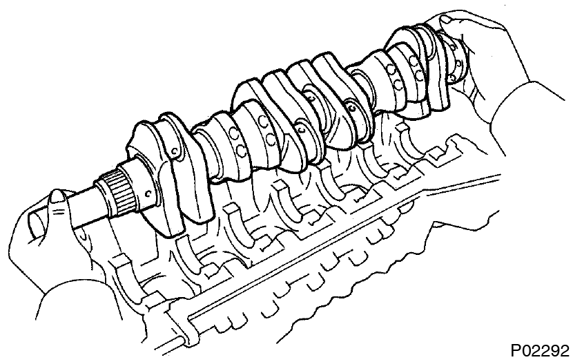
- Lift out the crankshaft
- Remove the upper bearings and upper thrust washers from the cylinder block.
Arrange the main bearing caps, bearings and thrust washers in the correct order. -
Remove oil nozzles (with relief valves)
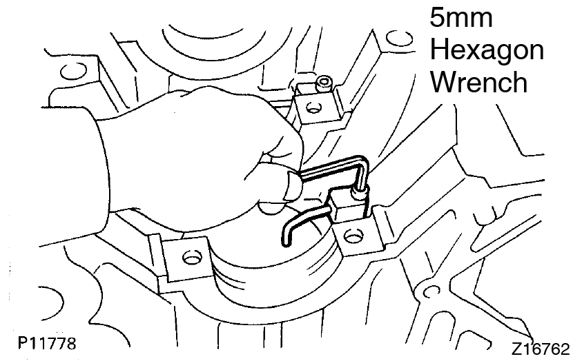 Using a 5 mm hexagon wrench, remove the bolt and oil nozzle. Remove the 6 oil nozzles.
-
Check fit between piston and piston pin
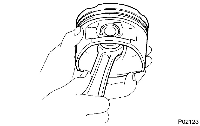 Try to move the piston back and forth on the piston pin.
If any movement is felt, replace the piston and pin as a set. -
Remove piston rings
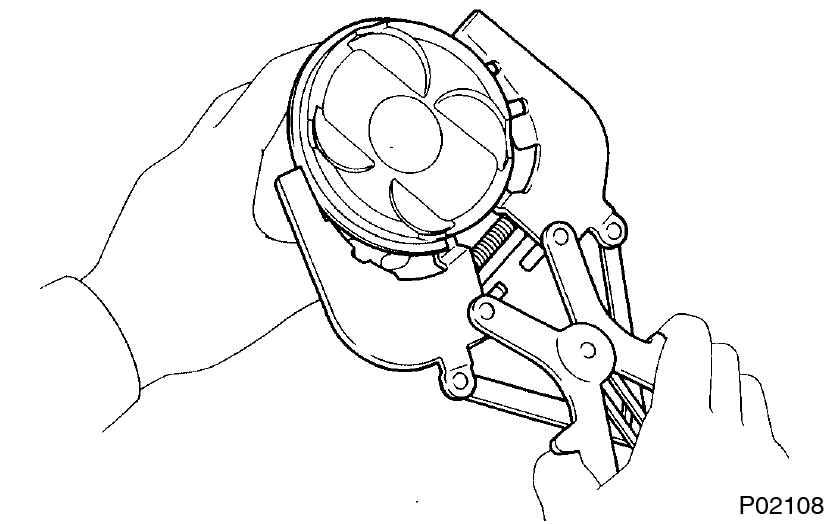
- Using a piston ring expander, remove the 2 compression rings.
- Remove the 2 side rails and oil ring expander by hand.
Arrange the piston rings in correct order only. -
Disconnect connecting ROD from piston
-
Using a small screwdriver, remove the 2 snap rings.
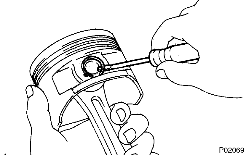
-
Gradually heat the piston to about 80°C (176°F).
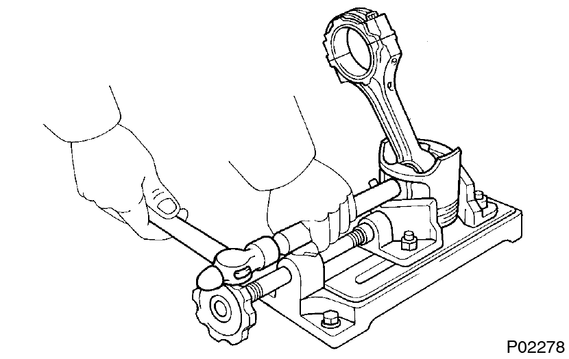
- Using a plastic-faced hammer and brass bar, lightly tap out the piston pin and remove the connecting rod.
- The piston and pin are a matched set.
- Arrange the pistons, pins, rings, connecting rods and bearings in the correct order.
-
Using a small screwdriver, remove the 2 snap rings.
This guide is based on the book edition Toyota (RM502U, 1997)
Volksbibliothek, info@volksbibliothek.com
Back Next